-
Name*
-
Phone*
-

Solution
Gold wire ball welding inner lead welding
-

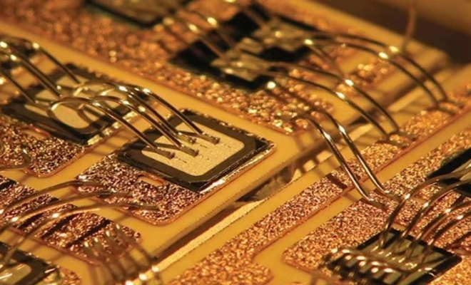
The welding process of connecting the metallized circuit leads or electrodes on a circuit chip to the metal lead frame or shell lead wire of the assembled chip. The inner lead welding process is a welding process after the completion of chip welding, commonly used methods include hot pressing welding, ultrasonic pressing welding, thermal ultrasonic welding (ball welding), planar welding, and beam lead welding.
View moreThe welding process of connecting the metallized circuit leads or electrodes on a circuit chip to the metal lead frame or shell lead wire of the assembled chip. The inner lead welding process is a welding process after the completion of chip welding, commonly used methods include hot pressing welding, ultrasonic pressing welding, thermal ultrasonic welding (ball welding), planar welding, and beam lead welding
Working principle of aluminum wire bonding machine
-
Working principle of aluminum wire bonding machine
View moreInstrument name: Ultrasonic aluminum wire pressure welding machine
Model: XE-2010
Aluminum wire bonding machine is an equipment used for important lead welding in semiconductor chip manufacturing. Its working principle is to weld metal wires (usually aluminum or copper) onto the metal pins on the chip surface. These metal wires are used to connect different parts of the chip, forming a circuit
Multi row solder pad shell packaging IC wire ball bonding technology
-
 View more
In the lead bonding of multi-layer and multi row solder pad shell packaging circuits, due to the high density of the bonding leads, the distance between the bonding leads is small, and the distance between the bonding points is also small. In the circuit bonding, it is necessary to control the position, quality, and arc of the bonding leads well, otherwise the circuit bonding cannot meet the requirements of practical use. The article discusses the arc control of gold wire ball bonding leads for high-density multi-layer and multi row solder pads ceramic shell packaging integrated circuits, as well as the quality issues of conventional ball bonding points for shell solder pads. By optimizing the arc form of bonding leads and adopting" Self mode" The planting ball bonding technology greatly improves the quality of circuit bonding, and the bonding leads meet the requirements of process control and practical use. At the same time, the density of bonding on the shell solder pad has also been improved
Application of Medium Voltage Technology in Gold Wire Ball Welding
-
View more
Gold wire ball soldering technology, also known as chip wiring technology, is a primary internal interconnection method that connects frame pins to the surface of the bare chip or the internal logic circuit of the device. This connection method connects the logic signal or electrical signal of the chip to the outside world. The schematic diagram of wire ball welding technology is as follows. The wire ball welding process is a solid-state welding process different from hot welding. Its principle is to output ultrasonic sine wave electrical signals through an ultrasonic generator, which are transformed into mechanical vibration through an ultrasonic transducer. The amplitude is amplified by an ultrasonic amplitude converter and transmitted to the welding cutter, causing friction on the metal contact surface. In the early stage of welding, the oxide film and impurities in the welding area are eliminated, and vibration friction allows for full contact between the two metals. During the welding phase, due to the high sound resistance at the interface between the two welds, local high temperatures are generated. In a short time, the high temperature in the welding area cannot be distributed in time, which causes the contact surface to melt rapidly. At the same time, the pressure electromagnet generates magnetic force under the condition of power on, and applies downward force to the cleaver, so that the two Metallic bonding bond together. When the ultrasonic Stopping power, let the pressure applied on the cleaver last for a period of time to solidify and form, so as to form a solid molecular chain, achieve the purpose of welding, form a solid mechanical connection, and realize welding


